DIGITAL FREQUENCY DISPLAY FOR VINTAGE RADIO EQUIPMENT
TYPE NFD-1

Thumbnail Pictures - Click to Enlarge
FREQUENCY DISPLAY UNIT
DIGITAL FREQUENCY DISPLAY FOR VINTAGE RADIO EQUIPMENT
TYPE NFD-1
Thumbnail
Pictures - Click to Enlarge
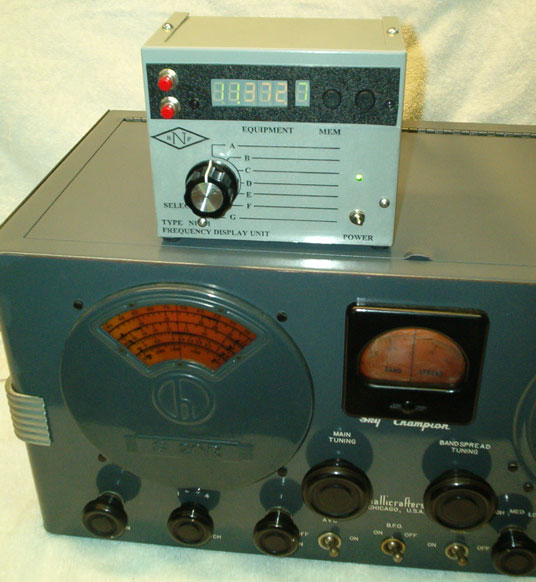
The National RF Type NFD-1 Frequency Display Unit
was designed for use with vintage and classic communications equipment, to display
the received or transmitted radio frequency. The unit incorporates an internal
processor that allows the intermediate frequency (IF) to be counted out by the
frequency counter. The resultant display is the actual frequency that the equipment
is receiving or operating at.
The unit consists of a high gain radio frequency amplifier that amplifies the
local oscillator signal of the radio to a level that the counter circuit will
count. Four separate memory channels are provided that allow the user to program
the unit for four different IF frequencies. Typically, vintage/classis receivers
may utilize IF frequencies of 165 KHz, 455 KHz, 1.8 MHz or 10.7 MHz. Although
not limited to these frequencies, each of the four memory channels may be programmed
for these IF frequencies, thus allowing the counter to count out these frequencies
and display the actual frequency of reception or operation. Or, if the user
desires, no IF offset may be programmed and a sense wire or whip antenna attached,
thus allowing the unit to display transmit frequencies of vintage transmitters
and transceivers. A front panel equipment selection switch allows a total of
7 pieces of equipment to be interfaced with the unit. The user simply selects
the equipment in use and selects the required memory channel to display the
operational frequency.
In addition to allowing programming for virtually any IF frequency up to about 55 MHz, the unit can be programmed to accommodate receivers that tune increasing frequency with a local oscillator that decreases in frequency. This is common on multi-conversion super-hetrodyne receivers, and particularly on the Collins S-Line equipment, where crystal controlled front-end converters feed a tunable IF strip. Furthermore, the unit will allow for the local oscillator to be either on the high side of the received frequency or the low side. On older receivers, where local oscillator stability may be an issue, the unit may be programmed to disable the Hundred Hertz digit, thus making 1 KHz the minimum frequency resolution. Usually, this is acceptable for unstable vintage equipment.
In order to sense
the local oscillator signal of the vintage/classic equipment, the user will
have to enter the radio equipment to install a sense wire loop near the oscillator
coils. Optionally, the user may have to install a low value coupling capacitor
to the oscillator circuit that will couple RF energy to the display unit. Interface
instructions for this operation are provided with the hardware, and recommendations
for which technique to use for various manufacturers of vintage equipment (National,
Collins, Hammarlund, etc). The input impedance of the frequency display unit
is sufficiently high that it will not detune the local oscillator that it is
coupled to, particularly if the interfacing cable is kept as short as practical
to minimize shunt cable capacitance.
| Counting Frequency Range: | 160 KHz to 55 MHz |
| Counter
Sensitivity for a stable 7 digit display: |
160 KHz to 10 MHz; -36dBm, typical 10 MHz to 25 MHz; -33dBm. Ave. 25 MHz to 35 MHz, -26dBm. Ave. 35 MHz; -22dBm, 45 MHz; -14dBm 55 MHz; -10dBm |
| Input Impedance: | Greater than 100,000 Ohms, not including shunt interconnecting cable capacitance |
| Optical Display: | 2 each digits, Megahertz display 3 each digits, Kilohertz display 1 digit, hundreds of Hertz display (programmable on or off) |
| IF Frequency Compensation/Offset: | 0 KHz to 54.850 MHz, (Programmable) |
| (Receiver local
oscillator may be either on the “high” side or “low” side of the received
frequency. Unit is programmed to select “side” as required. Unit may be programmed to accept increasing or decreasing local oscillator tuning for decreasing/increasing received frequency, respectively.) |
|
| Power: 12 volt DC wall-type power transformer provided, current draw 135 MA, typical. | |
| Equipment Interface: | 7 BNC rear panel female connectors selectable from front panel rotary switch. |
| Size: | 5 inches high 4 inches wide 3 inches deep |
Should you have further questions on this unit and its interface to specific classis/vintage radio equipment, please contact National RF, Inc. at the phone numbers listed on this website.
Price: $289.95 plus $7 UPS Ground shipping/handling charge, continental USA.
OVERSEAS CUSTOMERS: Please contact National RF for the shipping charge and delivery schedule to your country.
Home
-
Products
- Order
Form - Contact Us